Replacing a connector may seem straightforward, but choosing the correct substitute requires attention to both electrical and mechanical specifications. Here’s a step-by-step guide to help ensure compatibility and performance:
✅ 1. Identify the Original Connector Specifications
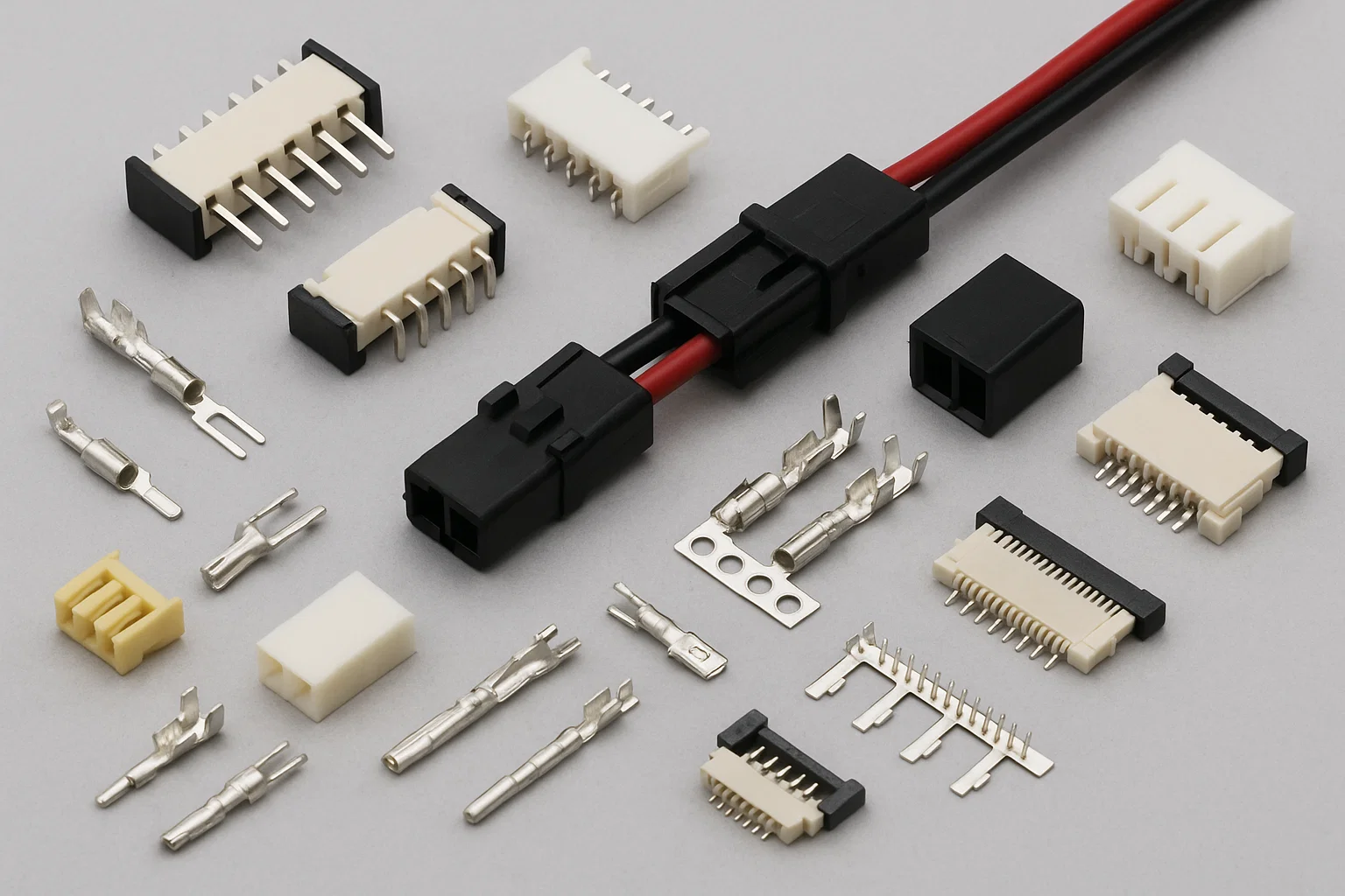
Start by gathering the following details from the datasheet or markings on the original connector:
- Connector type (e.g., wire-to-board, board-to-board, circular, FFC/FPC)
- Pitch (distance between pins or contacts)
- Number of positions (how many pins or terminals)
- Current and voltage rating
- Mounting type (e.g., through-hole, surface-mount, panel-mount)
- Termination style (crimp, solder, IDC, etc.)
- Mating style (plug/socket, header/receptacle)
- Locking mechanism (snap, latch, screw-lock)
✅ 2. Check Mechanical Compatibility
Ensure that the replacement:
- Matches the form factor and dimensions
- Has the same keying or polarization to prevent incorrect mating
- Fits into the existing enclosure or PCB footprint
- Is compatible with the cable or wire gauge used
If exact dimensions are unavailable, consider checking a 3D model or requesting a physical sample.
✅ 3. Match the Electrical Performance
The replacement connector should meet or exceed:
- Rated current and voltage
- Contact resistance
- Insulation resistance
- Dielectric strength
Always allow for safety margins, especially in power or high-speed applications.
✅ 4. Consider Environmental and Durability Requirements
Think about the application environment:
- Temperature range
- Vibration resistance
- IP rating (for waterproofing)
- UV resistance (for outdoor use)
- Number of mating cycles (durability)
✅ 5. Cross-Reference or Consult a Supplier
If the original brand or part number is known, try:
- Manufacturer’s cross-reference tools
- Distributor parametric search
- Consulting with a connector specialist
When a direct replacement is unavailable, an equivalent part from another brand may work — just verify all specs carefully.
No responses yet